
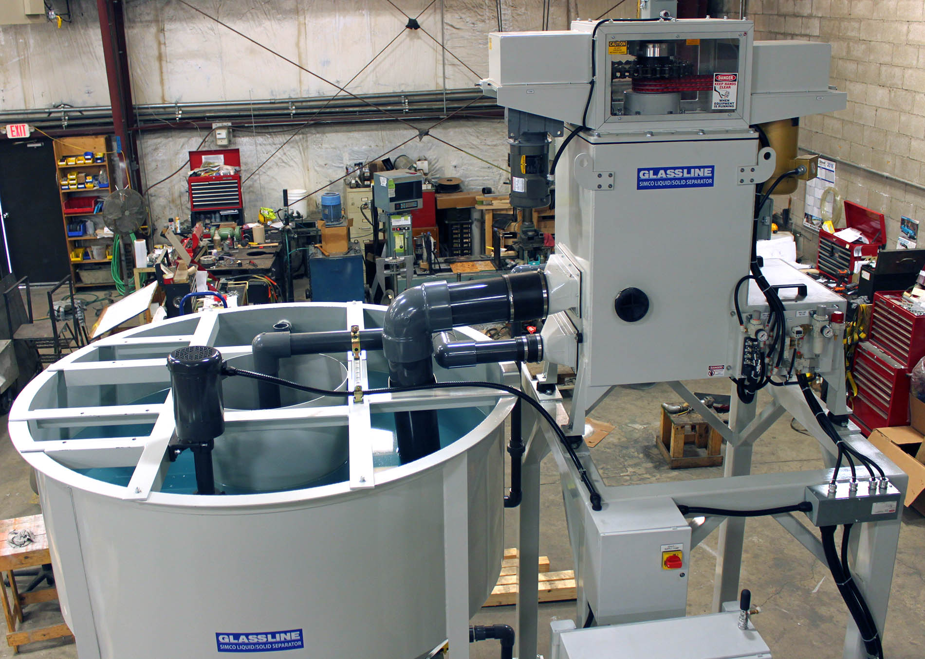
The Liquid Solid Separator, DL Series (Scraper Style), utilizes centrifugal force to separate solids from liquid, and periodically discharges the solids during the processing cycle.
The processing cycle of the separator is completely automatic.
Liquid containing particles of solids enters the centrifuge, via the feed inlet at the bottom of the machine. The slurry is forced upward through the feed pipe, where it is fed over a feed cone. At this point, the liquid is accelerated and dispersed by the centrifugal force generated by rotation of the rotor bowl. This force, which is up to 500 to 1800 times gravity, forces the solids to adhere to the inside wall of the bowl. Here, the clarified liquid is discharged through the clean liquid outlet port to a clean liquid tank for reuse.
As the slurry is processed, solids build-up on the inside wall of the rotor, or bowl, to the point that cleaning the bowl is required.
The point when a cleaning cycle is to be initiated is an automatic function of the centrifuge, through its controls.
Periodically during the process, bowl rotation is decelerated for a short period of time. The bowl is then accelerated back to normal speed. During re-acceleration, the current limit of the bowl drive motor is monitored by the motor controller.
As the build-up of solids increase during the process, more current is required to accelerate the bowl to normal speed each time a monitoring period occurs. When preset current limits are met or exceeded, the controls initiate a cleaning cycle.
When the solid to liquid ratio is low, considerable time could elapse before a cleaning cycle is initiated by the load sensing control. When this condition occurs, a timing function in the program over-rides the current limit control feature and initiates the cleaning cycle.
This prevents the solids on the rotor wall from becoming overly compact and difficult to remove.
When a cleaning cycle is initiated, bowl rotation is stopped and any remaining liquid left in the bowl drains onto the drain plate and is returned to the dirty liquid feed tank.
At this point, a cylinder operated rotor lock mechanism is engaged to prevent bowl rotation. The drain plate actuator is then energized to retract the drain plate and expose the discharge area for the elimination of the collected solids. The scraper clutch is pressurized and the scraper motor is energized. Rotation of the scraper removes the solids from the inside wall of the rotor bowl. The removed solids are then discharged through the bottom of the bowl into a suitable receptacle for disposal.
Safety factors have been provided to prevent damage to the machine components during the cleaning cycle.
- The air clutch has been provided to allow for mechanical slippage between the scraper drive shaft and the scraper motor drive assembly, should the cleaning load be excessive.
- A reversing feature has been provided in the controls of the equipment whereby the scraper drive motor will periodically change rotational directions at timed intervals. When solids are difficult to remove, and a pre-set current limit of the scraper drive motor has been exceeded, reversal of the scraper drive motor will also be initiated. This reversal feature allows stubborn solids to be broken loose and the cleaning cycle completed.
At the end of the cleaning cycle, the scraper clutch is de-energized, the rotor lock is withdrawn, and the drain plate is returned to its original position. The liquid solid separating cycle may then be repeated. NOTE: It is normal function of the separator to go through a complete cleaning cycle each time the machine is started or stopped, under normal conditions.
The cleaning cycle will not be functional if the emergency stop is activated, a motor drive fault occurs, a power failure occurs, or if air pressure drops below 50 psi. As soon as all of the above conditions are rectified, the machine start cycle should be actuated to initiate a cleaning cycle. This will prevent the accretion of solids to the bowl.
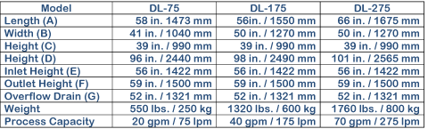
TECHNICAL SPECIFICATIONS for Model Simco DL-275XL (Automatic)
- Speed Capability 2000 RPM
- Rotor Volume 1525 cu. in., 6.6 Gallons
- Maximum Feed Rate 70 GPM
- Drive Motor 5 HP, TEFC, 380V, 3 Phase, 50Hz, 1730 RPM
- Solids Discharge Automatic
- Maximum Operating Temperature 194ºF
SUPPLEMENTARY EQUIPMENT
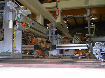
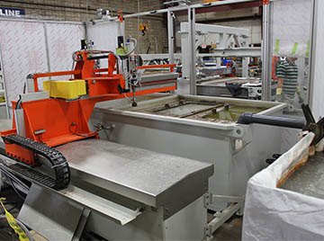
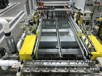
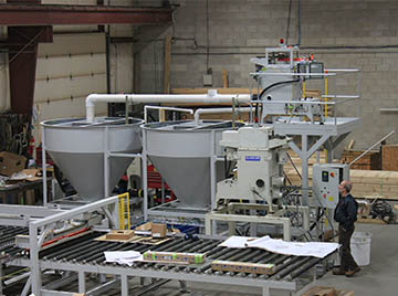
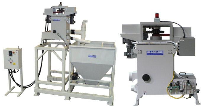
Various tank systems and supplementary equipment are offered to provide a complete filtration system to our customers. A standard tank configuration is shown below.
Standard Configuration

Available Options
- Stainless Steel Housing and or bowl
- Galvanized Steel Housing
- Quick connect plug in connectors to electrical panel
- Solids Sensor
- Tray position sensor
- Bowl rebuild exchange program